- Name of Project:
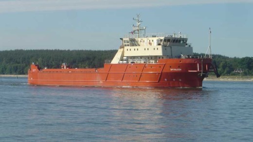
Design of a Knuckle Jib Crane - Scope of Work: Designed according API spec 2-c, the crane has been constructed and currently installed on MV DP CIRRUS. The rate is 35t @ 20m, sea state 0. Capability charts are available for detarating vs sea states.
Design of an Offshore Knuckle Jib Crane
| Crane type: | VM BUAR 1100000 R4 20 | List-trim: | 5° – 2° |
| Desig rules: | API spec 2C for offshore pedestal mounted crane six edition, march 2004 | Tank Volume: | 3500lt max |
| SWL main winch: | 35 ton single line at 8.5 – 20m | Voltage: | 440 V |
| Working radius max: | 20 m | Wire diameter: | 44 mm |
| Working radius min: | 8.5 m | Wire type: | non rotating, galvanized |
| Slew sector: | 360° unlimited | Wire capacity: | 500 m |
| Slew speed: | 0.7 rpm | Total weight: | abt 90 ton |
The crane is designed for long time offshore operations.
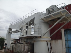
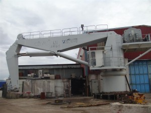
The cranes main components is a foundation welded to the vessels hull. A rotating tower is installed on top of foundation. The main boom is connected to the front of the tower with a knuckle jib installed on the outer end. Main winch is installed on top of a platform hinged to the aft section of the tower.
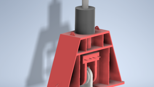
The crane foundation is made of steel plates rolled to a cylindrical shape. On top of the cylinder a flange is welded on to make a support for the slew bearing. On the lower section a hatch is installed to enter the inner side of the foundation.
The crane tower is made of steel plates and profiles shaped to a cylindrical shape. On the lower and of the cylinder a flange is welded on to make to make a support for the slew bearing. On the top section of the tower solid plates are welded to make eyes for connection of boom. In the front section very solid plates are installed for mounting of the lower end of boom-tower hydraulic cylinders.
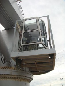
On the middle left side section a cabin support is welded on the tower structure. Round steel pipes are installed to protect the cabin and the crane operator. A ladder is installed to ensure a safe and easy entry to the cabin platform and tower roof.
A well dimensioned door is installed on the left side of the tower just above the platform to enter the inner side of the tower. The inside of the tower contain the hydraulic oil tank, pumps, control valves and electrical cabinets. The slewing gears/motors are also installed inside the tower.
The main boom is made of steel plates and profiles welded together to form a square box with inside stiffener plates to absorb the local forces from the boom-tower cylinders, knuckle jib and knuckle jib cylinders. On the both ends solid steel plates are welded for connection on the tower and knuckle jib.
Hydraulic cylinders are connected to the crane structures with solid bolts and are equipped with spherical bearings.
On the outer end a wire sheave is installed to guide the wire out to the knuckle jib. The sheave is connected to the bracket by means of a solid steel bolt. The brackets are welded to the boom structure.
The knuckle jib is made of steel plates and profiles welded together to form a square box with inside stiffener plates to absorb the local forces from the boom and main jib cylinders.
On the middle part a wire sheave is installed to guide the wire out to the knuckle jib end. The sheave is connected to the brackets by means of solid steel bolt with a load sensing sensor inside. The bracket is welded to the jib structure. On the outer end of knuckle jib 2 wire sheaves are installed to guide the wire out independent of the jib angle.
The main winch is made of steel plates and profiles that shapes the drum, side flanges and foundations. The winch is designed for general load handling up to SWL = 35ton.
The 35ton winch is equipped with 4 hydraulic motors and planetary gearboxes with brakes. The drive moment is transmitted from the gear pinion to the cog wheel installed on the drum.
Design of a Knuckle-Jib Crane


